This tutorial covers how to build an IoT controlled RGB LEDs (such a LEDs strip) using ESP32 or ESP8266 and Firebase. This is an interesting project because through it, it is possible to explore how to use IoT. Some years ago it was almost impossible to build an IoT controlled RGB LEDs, now, as you will see, it is very easy. In this IoT project, we will use the power of Google Firebase to control RGB LEDs using ESP32 or ESP8266. Briefly, Google Firebase cloud is a platform that provides several services such as Authentication, realtime database and so on. To build this IoT project we will use realtime database. The result is shown in the video below:
To control LEDs using Firebase realtime database, we have to follow these two steps:
- configure the ESP32/ESP8266 to connect to Google Firebase real-time database
- configure the Firebase real-time database
Configuring ESP32 (or ESP8266) to connect to Google Firebase real-time database
In this first step, it is necessary to connect ESP32 to Firebase database so that this device receives the data from the database as soon as we modify them. To achieve it, first we have to connect the ESP8266 to the Wifi:
#include <ESP8266WiFi.h>

void connectWifi() {
  // Let us connect to WiFi
  WiFi.begin(ssid, password);

  while (WiFi.status() != WL_CONNECTED) {
    delay(500);
    Serial.print(".");
  }

  Serial.println(".......");
  Serial.println("WiFi Connected....IP Address:");
  Serial.println(WiFi.localIP());
}
where connectWifi() is called in the setup() as we will see later and the ssid and password are the WiFi ssid and the related password.
Circuit diagram
The circuit diagram to connect RGB LEDs to ESP8266 (or ESP32) is shown below:
This IoT controlled LEDs project uses Neopixels LEDs, but we can use other kinds of LEDs. The same steps can be applied even if you change the LEDs you use.
Programming the ESP8266 to connect to Firebase
This is the core of the project. To connect the ESP32 to Google Firebase realtime database we will use a Firebase library that simplifies the project. Go to Sketch->Include Library->Manage Libraries and look for Firebase library:
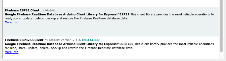
Select the library according to the device you are using ESP32 or ESP8266 and you’re ready! The code below shows how to connect the ESP8266 to Google Firebase:
#include "FirebaseESP8266.h"

FirebaseData firebaseData;

void setup() {
  Serial.begin(9600);
  connectWifi();
  Firebase.begin("firebase_url", "your_firebase_API_key");
}
At line 8, the code sets up the connection between ESP8266 and Firebase. Two parameters are necessary: the firebase_url and the firebase_API_key. You will see later how to get it from Firebase console after we have configured the Firebase project. Finally, it is necessary to receive data from Firebase realtime database:
void loop() {

  if (Firebase.getInt(firebaseData, "/red")) {
   if  (firebaseData.dataType() == "int") {
      int val = firebaseData.intData();
      if (val != redValue) {
        redValue = val;
        setLedColor();
      }
    }
  }

  if (Firebase.getInt(firebaseData, "/green")) {
   if  (firebaseData.dataType() == "int") {
      int val = firebaseData.intData();
      if (val != greenValue) {
        greenValue = val;
        setLedColor();
      }
    }
  }

  if (Firebase.getInt(firebaseData, "/blue")) {
   if  (firebaseData.dataType() == "int") {
      int val = firebaseData.intData();
      if (val != blueValue) {
        blueValue = val;
        setLedColor();
      }
    }
  }
}
A few things to note. First, to control an IoT RGB LEDs it is necessary to use three components (red, green, blue). The Second thing to notice: the code above gets the reference to the data stored in Firebase realtime database using:
Firebase.getInt(firebaseData, "/red")
then, it is necessary to verify that the value is an integer:
if  (firebaseData.dataType() == "int") {
  ....
}
and finally, the code retrieves the value:
int val = firebaseData.intData();
The final code is shown below:
#include "FirebaseESP8266.h"
#include <ESP8266WiFi.h>
#include <Adafruit_NeoPixel.h>

#define PIN D1
#define NUM_LEDS 8

const char* ssid = "your_ssid";
const char* password = "your_wifi_passowrd";

FirebaseData firebaseData;

Adafruit_NeoPixel leds(NUM_LEDS, PIN, NEO_GRB + NEO_KHZ800);

// Current color values
int redValue = 0;
int greenValue = 0;
int blueValue = 0;

void setup() {
  Serial.begin(9600);
  connectWifi();
  leds.begin();

  Firebase.begin("https://xxxx.firebaseio.com/", "wDsHB30jVN554CA********");
}

void loop() {

  if (Firebase.getInt(firebaseData, "/red")) {
    if  (firebaseData.dataType() == "int") {
      int val = firebaseData.intData();
      if (val != redValue) {
        redValue = val;
         setLedColor();
      }
    }
  }

  if (Firebase.getInt(firebaseData, "/green")) {
    if  (firebaseData.dataType() == "int") {
      int val = firebaseData.intData();
      if (val != greenValue) {
        greenValue = val;
        setLedColor();
      }
    }
  }

  if (Firebase.getInt(firebaseData, "/blue")) {
    if  (firebaseData.dataType() == "int") {
      int val = firebaseData.intData();
      if (val != blueValue) {
        blueValue = val;
        setLedColor();
      }
    }
  }
}

void connectWifi() {
  // Let us connect to WiFi
  WiFi.begin(ssid, password);

  while (WiFi.status() != WL_CONNECTED) {
    delay(500);
    Serial.print(".");
  }

  Serial.println(".......");
  Serial.println("WiFi Connected....IP Address:");
  Serial.println(WiFi.localIP());

}

void setLedColor() {
  for (int i=0; i < NUM_LEDS; i++)
    leds.setPixelColor(i, leds.Color(redValue, greenValue, blueValue));
   leds.show();
}
If you are interested you can discover how to integrate ESP8266 and Alexa so that you can control devices using voice commands.
Configuring the Firebase realtime database
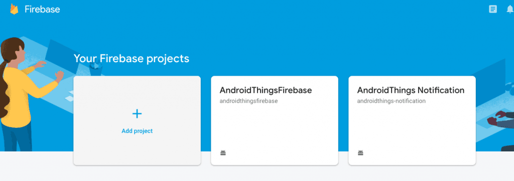
In this second steps in building an IoT controlled RGB LEDs, we will configure the Firebase realtime database. If you don’t have an account, before starting it is necessary to create one for free. Then go to the Firebase console and start adding a new project:
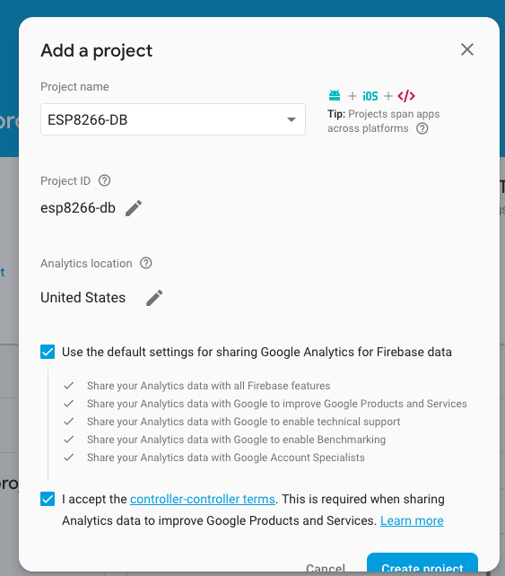
and then add a new project as shown below:
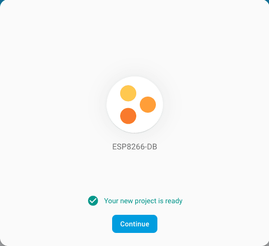
If everything goes well, then the new Firebase project is created:
Then it is time to create the Firebase database:

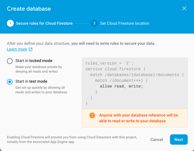
It is important you set the database in test mode:
Then when all these steps are complete, select the realtime database and start adding fields as shown below:
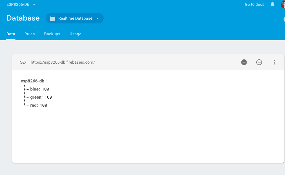
Now the last two steps. First, in the Rules, you have to set all the values to true and then it is necessary to retrieve the values to use in the ESP8266 code shown above:
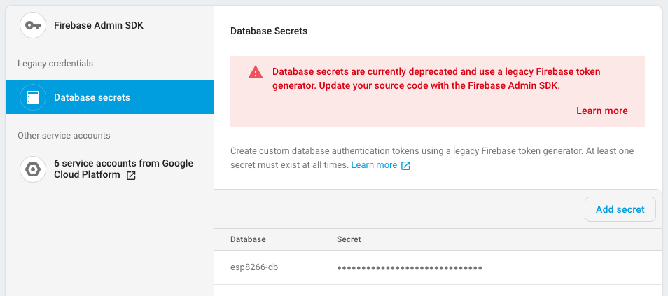
The url is shown in the picture above https://xxxx.firebaseio.com and the API Key is in Project settings -> Services account->Database secrets.
That’s all. You can run and test the project.
Summary
This tutorial has shown how to build an IoT controlled RGB LEDs using Firebase realtime database and ESP32 or ESP8266. As you have seen, it is very easy and with a few lines of code you can control remotely RGB LEDs.
| Published on .NET Code Geeks with permission by Francesco Azzola, partner at our NCG program. See the original article here: test
Opinions expressed by .NET Code Geeks contributors are their own. |