IoT MQTT protocol tutorial describes to control a remote peripheral. We have already covered the MQTT protocol and how it works and we already know the IoT MQTT is used to send data from remote sensors. Just to recap briefly MQTT is a lightweight protocol used in the telemetry. Several IoT platforms support MQTT to exchange data with remote IoT boards and sensors. Usually, IoT boards use MQTT to connect to the IoT platforms that acquire information.
Project description
In this project, we use MQTT in a different way or in other words, we want to control an IoT board (like MKR1000) using MQTT. The target of this project is controlling an RGB Led Matrix remotely using MQTT.
To build this project, we will use:
- Arduino MKR1000
- 4×4 RGB Led Matrix
The MKR1000 will connect to Ubidots cloud platform using MQTT. This project is divided into two steps:
- Configure the Ubidots to handle the RGB color components using the web interface
- Develop an MQTT client to connect to Ubidots and manage the RGB Led Matrix
At the end of this project, we control the RGB Led matrix remotely using Ubidots web interface.
Configure the IoT board
In this first step, we will configure the Ubidots interface to handle the three color components. We will use sliders to control them. Let us begin. Before continuing you have to create a free account using this link. Log into the application and click on the Device to create a new device.
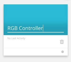
We used RGB Controller as the device name. A device acts as a data container where we can group variables that hold the data exchanged. Once the device is ready, we can start adding a new variable:
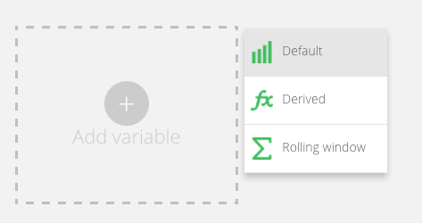
We create three variables called:
- redColor
- greenColor
- blueColor
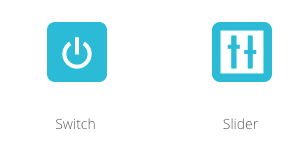
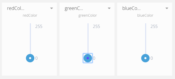
Now it is time to create the dashboard that we will use to control these variable values. Go to Dashboard and click on add. Give a name to your dashboard and start adding controls. In this project, we add sliders so click on add new widget and then on slider:
Select the device (aka the datasource) previously configured:
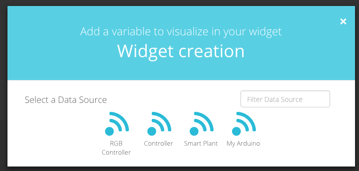
Select the RGB Controller and you will see three variables:
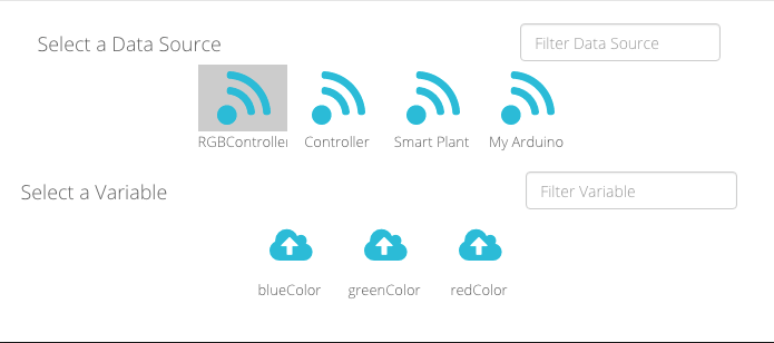
Select one of them and repeat the process for all three variables. At the end, you will have a dashboard that looks like:
How to implement a client to handle the IoT MQTT protocol
Once the IoT platform is configured we can focus our attention on the IoT MQTT client. This client receives the data from the platform and manages the RGB Led matrix. To create the client, we use the following libraries:
- Adafruit Neomatrix
- MQTT Client (you can download it from Arduino Library Manager)
The first step is initialized the Neomatrix providing a set of information like the matrix width and height and the pin number. In our case, the RGB Led matrix is connected using MKR PIN 5.
Adafruit_NeoMatrix matrix = Adafruit_NeoMatrix(4, 4, 5,
                           NEO_MATRIX_TOP     + NEO_MATRIX_RIGHT +
                           NEO_MATRIX_COLUMNS + NEO_MATRIX_PROGRESSIVE,
                          NEO_GRB + NEO_KHZ800);
Notice the first three parameters represent the number of LEDs in a row and in a column. Using matrix instance we can color the matrix.
Let us implement the MQTT client. This project uses MKR1000 so a WIFI connection:
WiFiClient net;
MQTTClient mqttClient;

void setup() {
  Serial.begin(115000);
  Serial.println("Configuring the net...");
  WiFi.begin("your WiFi SID", "your WiFi password");

  while (WiFi.status() != WL_CONNECTED) {
    Serial.print(".");
    delay(1000);
  }
  Serial.println("Begin...");
  mqttClient.begin("mqtt://things.ubidots.com", net);
  matrix.begin();
  connect();
}
In the setup() method, we simply initialize the WiFi connection and the mqttClient. To initialize the mqtt client we have to set the MQTT server (Ubidots server address) and the net.
The connect() method handles the connection and the MQTT topic subscription. According to the Ubidots docs, each variable defined in the datasource (aka device) has it is own topic:
/v1.6/devices/_device_name/_variable_name/lv
Notice that the lv, at the end of the topic, stands for last value. In other words, we are interested only on the last variable value to control the RGB LED matrix. In this project, the application has to subscribe to the following topics:
/v1.6/devices/RGBController/redColor/lv
/v1.6/devices/RGBController/greenColor/lv
/v1.6/devices/RGBController/blueColor/lv
So the connect() method is:
void connect() {
  Serial.println("Connecting to MQTT....");
  if (mqttClient.connect("YOUR_UNIQUE_ID", "YOUR_UBIDOTS_TOKEN", "")) {
    Serial.println("MQTT client connected");
    int result = mqttClient.subscribe("/v1.6/devices/RGBController/redColor/lv");
    Serial.println(result);
    Serial.println("Subscribed red topic.");
    int result1 = mqttClient.subscribe("/v1.6/devices/RGBController/greenColor/lv");
    Serial.println(result1);
    Serial.println("Subscribed green topic.");
    int result2 = mqttClient.subscribe("/v1.6/devices/RGBController/blueColor/lv");
    Serial.println(result1);
    Serial.println("Subscribed blue topic.");
  }
  else {
    Serial.println("######### Client not connected ########");
  }
}
Once the application is connected to the MQTT server and subscribed to the variable topics, we have to implement the method that listens to the values coming from the MQTT server. To this purpose, we have to implement a method named messageReceived(String topic, String payload, char * bytes, unsigned int length). In this method the application has to do the following tasks:
- identify the topic that holds the message
- convert the message to the color component value
- control the RGB LED matrix setting the new color
This is the method implementation:
void messageReceived(String topic, String payload, char * bytes, unsigned int length) {

  if (topic.indexOf("redColor") >= 0) {
    red = atoi(bytes);
  }
  else if (topic.indexOf("greenColor") >= 0) {
    green = atoi(bytes);
  }
   else if (topic.indexOf("blueColor") >= 0) {
    blue = atoi(bytes);
  }
  matrix.fillScreen(matrix.Color(red,green,blue));
  matrix.show();
}
That’s all. In the last two lines of the method, we use the instance of matrix to fill the RGB LED matrix with the color identified by red, green, blue component and we show it.
Conclusion
At the end of this post, hopefully, you have gained the knowledge about IoT MQTT protocol and how to use it to control remote peripheral.
| Reference: | IoT MQTT protocol tutorial: Control remote peripherals in IoT project from our JCG partner Francesco Azzola at the Surviving w/ Android blog. |