Build your own robot arm – remote control
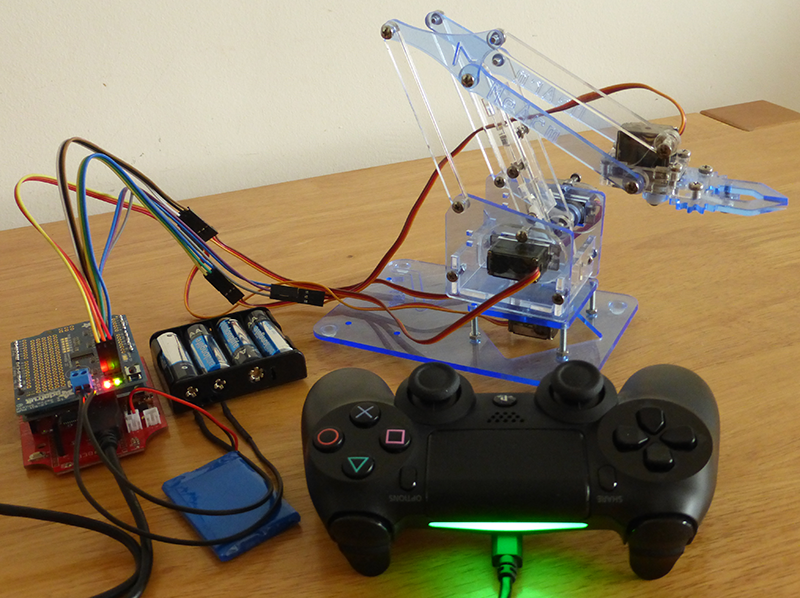
In previous installment of this micro series, I discussed the way to control all the servos at once. Programmatically without any outside interaction. This just won’t do. Final step in this project is obviously remote control that is going to add another level of complexity and also fun. Join me and lets take a look at what it takes to hook this MeArm robot arm to PlayStation 4 controller. If you missed the introduction to programming of this arm check out my previous post Build your own robot arm – programming.
What you need
Once again, you will need to get some extra hardware to facilitate the remote control of servos. Good news for the beginners is that no soldering is required for this part of project.
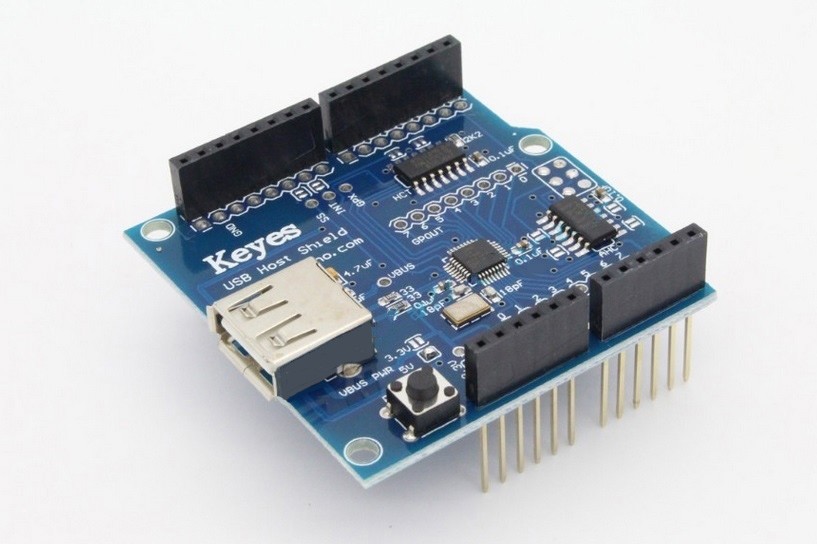
- USB Host shield 2.0 (available here – roughly 23 €)
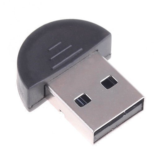
- Bluetooth adapter (like this one – roughly 8 €, but it can be purchased cheaper from China)
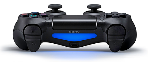
- PlayStation 4 controller (available on Amazon – roughly 50 €, but probably it is a part of your gaming system already :) )
- An Arduino IDE
USB Host shield
USB Host shield is an integral part at this stage. Great thing about this shield is its versatility. You can either use wired mode and plug your controller into the shield using the charging USB cable or plug in the Bluetooth adapter and use it in wireless mode. Another great thing is that you can use also Xbox controller in a same way. Given the architecture of these shields you are going to stack these shields. First, this shield goes on top of your Arduino board.
Based on the type of your connection you should plug in your Bluetooth adapter now. Now stack the servo shield on top and connect all the servos to it. There are holes in the base that are used to mount the Arduino board in case you want to gain some extra stability with your build. Once everything is wired and connected properly you can move on to the next step – programming.
Programming
Before we dive into code lets outline the vision for the final design. I personally really love the way PS4 controller was designed and how it feels in my hands. Among many features this piece of tech offers I am going to be using following controls visible from the top:
- left stick
- movement along the Y axis
- opens and closes the gripper
- movement along the Y axis
- right stick
- movement along the X axis
- rotates the arm to the left or to the right
- movement along the Y axis
- extends and retracts the arm
- movement along the X axis
- X button
- resets the arm to its initial position
- rumble
- turns on when any physical limit (determined in chapter Research & development) is reached
And following controls visible from the front:
- triggers
- left trigger
- lowers the arm
- right trigger
- rises the arm
- left trigger
- LED light
- Because we all know that unless it blinks like crazy it ain’t cool enough :)
- Blue blinking light
- controller is searching for connection / connecting
- Blue steady light
- controller is connected and ready to go
- Green steady light
- robot arm is in the initial position and ready for operation
- Red blinking light
- turns on when any physical limit (determined in chapter Research & development) is reached
Putting it all together
Once again, all the heavy lifting is done for us by a library. We will need Revision 2.0 of USB Host Library for Arduino by Circuits@Home. Special thanks goes to Kristian Sloth Lauszus and team around him as well as all the contributors to the project for creating and maintaining really sweet library to use this shield. Check out GitHub repository for this library, download it and add it to your library collection in Arduino IDE. As usual, the example section is your best friend to get acquainted with a new library or framework.
The sketch I ended up with is a bigger one so lets break it down. We need 4 variables to accurately track current position of each servo and their default positions for resting purposes. First of all I decided to use USB as a way of connecting my controller during development so the setup method initiates the connection and sets the initial values. Then I defined a dedicated method per servo to control its movement and handle checks when physical limits are reached. I know this code can be reduced but for the sake of clarity and easier maintenance / readability I went for 4 dedicated methods (my board has enough memory to handle this so there were no problems with the size).
Loop method handles inputs from the controller and based on reaching the physical limits of the robot arm triggers / turns off rumble and status LED. You should be familiar with last two bits since they were mentioned in my previous post. First the method resetting the arm to its initial position and utility method to simplify the control of any of the servos. And that’s it! With assembled robot arm, shields properly stacked and servos properly wired you can upload your sketch, connect the controller and enjoy your play time :) .
Robot arm control using PS4 controller via USB sketch
#include <Wire.h>
#include <PS4USB.h>
#include <Adafruit_PWMServoDriver.h>

Adafruit_PWMServoDriver pwm = Adafruit_PWMServoDriver();
USB Usb;
PS4USB PS4(&Usb);

#define BASE 0
#define HEIGHT 1
#define LENGTH 2
#define GRIP 3

float base_init = 1440;
float height_init = 1675;
float length_init = 1440;
float grip_init = 2155;

float base_current = base_init;
float height_current = height_init;
float length_current = length_init;
float grip_current = grip_init;

float SERVOFREQ = 50;
float pulseconstant;
boolean limit_reached = false;

void setup() {
    Serial.begin(9600);

    if (Usb.Init() == -1) {
        while (1);
    }

    pulseconstant = (1000000/SERVOFREQ)/4096;

    pwm.begin();
    pwm.setPWMFreq(SERVOFREQ);

    servoWrite(BASE, base_init);
    servoWrite(HEIGHT, height_init);
    servoWrite(LENGTH, length_init);
    servoWrite(GRIP, grip_init);

    PS4.setLed(Green);
}

void handleBase() {
    // check to stop the servo
    if (base_current - 10 <= 525 && PS4.getAnalogHat(RightHatX) > 220) {
        limit_reached = true;
        return;
    } else if (base_current + 10 >= 2355 && PS4.getAnalogHat(RightHatX) < 35) {
        limit_reached = true;
        return;
    } else {
        // handle movement
        if (PS4.getAnalogHat(RightHatX) < 35) {
            base_current += 10;
        }
        if (PS4.getAnalogHat(RightHatX) > 220) {
            base_current -= 10;
        }
    }
}

void handleReach() {
    // check to stop the servo
    if (length_current - 10 <= 525 && PS4.getAnalogHat(LeftHatY) > 220) {
        limit_reached = true;
        return;
    } else if (length_current + 10 >= 2355 && PS4.getAnalogHat(LeftHatY) < 35) {
        limit_reached = true;
        return;
    } else {
        // handle movement
        if (PS4.getAnalogHat(LeftHatY) < 35) {
            length_current += 10;
        }
        if (PS4.getAnalogHat(LeftHatY) > 220) {
            length_current -= 10;
        }
    }
}

void handleHeight() {
    // check to stop the servo
    if (height_current - 10 <= 1100 && PS4.getAnalogButton(L2) > 220) {
        limit_reached = true;
        return;
    } else if (height_current + 10 >= 2250 && PS4.getAnalogButton(R2) > 220) {
        limit_reached = true;
        return;
    } else {
        // handle movement
        if (PS4.getAnalogButton(L2) > 220) {
            height_current -= 10;
        }
        if (PS4.getAnalogButton(R2) > 220) {
            height_current += 10;
        }
    }
}

void handleGripper() {
    // check to stop the servo
    if (grip_current - 10 < 1800 && PS4.getAnalogHat(RightHatY) < 220) {
        return;
    } else if (grip_current + 10 > 2155 && PS4.getAnalogHat(RightHatY) > 35) {
        return;
    } else {
        // handle movement
        if (PS4.getAnalogHat(RightHatY) < 35) {
            grip_current -= 10;
        }
        if (PS4.getAnalogHat(RightHatY) > 220) {
            grip_current += 10;
        }
    }
}

void loop() {
    Usb.Task();

    if (PS4.connected()) {
        limit_reached = false;

        if (PS4.getButtonClick(CROSS)) {
            resetMeArm();
        }

        handleBase();
        handleReach();
        handleHeight();
        handleGripper();

        if (!limit_reached) {
            PS4.setLed(Green);
            PS4.setRumbleOff();
            PS4.setLedFlash(0, 0);
        } else {
            PS4.setLed(Red);
            PS4.setRumbleOn(RumbleHigh);
            PS4.setLedFlash(10, 10);
        }
    }

    delay(5);
    servoWrite(BASE, base_current);
    servoWrite(LENGTH, length_current);
    servoWrite(HEIGHT, height_current);
    servoWrite(GRIP, grip_current);
}

void resetMeArm() {
    servoWrite(BASE, base_init);
    servoWrite(HEIGHT, height_init);
    servoWrite(LENGTH, length_init);
    servoWrite(GRIP, grip_init);

    base_current = base_init;
    height_current = height_init;
    length_current = length_init;
    grip_current = grip_init;
}

void servoWrite(uint8_t n, float pulse) {
    float pulsetick = pulse/pulseconstant;
    pwm.setPWM(n, 0, pulsetick);
}
Independent power source
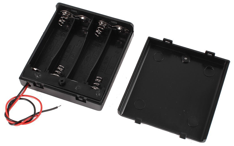
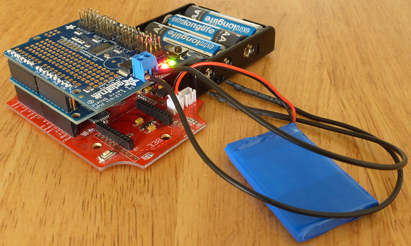
Last thing to consider in this project is power supply. Unless you are fine with being bound to some wired plug to power the servo shield I would suggest using batteries. No need to do anything fancy here and simple battery holder will do. I was using 4 AA batteries with battery holder like the one depicted below. I was able to complete this project using only 4 batteries without draining all the juice out of them. And since the servo shield has the screw terminal block connecting and disconnecting of your battery set is extremely simple. This combined with wireless joystick makes this robot arm nice portable (I took it to the coffee shop to show it to my friends – you should have seen the faces of the people sitting near our table :) ).
The end result
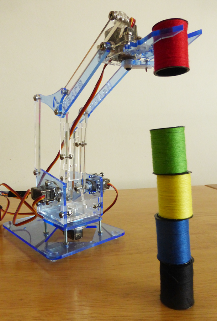
At this point there is nothing left to do but enjoy the fruits of your labor.
Stack it!
Wire it up!
Use it!
Conclusion
So this was my final post regarding this project and I must say I am quite happy with the results. I was expecting it to take much more of my time since it was my first time dealing with servos, soldering and remoting in general. However, the biggest delays were caused by waiting for delivery of individual part. I decided to take it one stage at a time so I wouldn’t order servo shield until I had the arm assembled and was comfortable with controlling servos and so on.
In case you have kids and want to get them to play with something less common and even educational this is a project to go for. There is a lot to be learned both for younger and older audience. Since use can use Raspberry Pi to control the arm it is easy to set up Scratch so even a kid can do his or hers programming and see how it affects the machine. And once you are done with this project you can sell / give it to someone else like I did so the pleasure of this kind of learning can be shared with others.
In case you decide to go for it and embark on this project do let me know how it went in the comment section.
| Reference: | Build your own robot arm – remote control from our JCG partner Jakub Stas at the Jakub Stas blog. |

