Learn how to create a sensor project in this guest post by Peter Wahr, an IoT expert.
The development of a sensor is broken down into six steps. Here’s a simple overview:
- Firstly, you will set up the basic structure of a console application.
- Then, you will configure the hardware and learn to sample sensor values and maintain a useful historical record.
- After adding HTTP server capabilities and other useful web resources to the project, you will publish the sensor values collected on the internet.
- You will then handle the persistence of sampled data in the sensor, so it can resume after outages or software updates.
- The next step will teach you how to add a security layer requiring user authentication to access sensitive information on top of the application.
- In the last step, you will learn how to overcome one of the major obstacles in the request/response pattern used by HTTP, that is, how to send events from the server to the client.
This tutorial, however, will focus only on the first two steps; to know more, you can refer to the book, Learning Internet of Things.
Preparing Raspberry Pi for sensor project
To configure Raspberry Pi, refer to http://www.raspberrypi.org/help/faqs/#buyingWhere.
In this tutorial, you will see the use of Model B with the following:
- An SD card with the Raspbian operating system installed
- A configured network access, including Wi-Fi, if used
- User accounts, passwords, access rights, time zones, and so on, all configured correctly
The sensor project will be developed on a remote PC using C#, as it’s a modern programming language that allows complete flexibility with IoT. It also allows you to interchange code between Windows, Linux, Macintosh, Android, and iOS platforms.
Once a project is compiled, executable files are deployed to the corresponding Raspberry Pi and then executed. Since the code runs on .NET, any language out of the large number of CLI-compatible languages can be used.
Tip
Development tools for C# can be downloaded for free from http://xamarin.com/.
To prepare Raspberry for the execution of the .NET code, you need to install Mono, which contains the Common Language Runtime for .NET that will help you run the .NET code on Raspberry. This can be done by executing the following commands in a terminal window in Raspberry Pi:
$ sudo apt-get update
$ sudo apt-get upgrade
$ sudo apt-get install mono-complete
Your device is now ready to run the .NET code.
Hardware: Sensor used in Raspberry Pi IoT project
The sensor prototype will measure three things: light, temperature, and motion. To summarize, here is a brief description of the components:
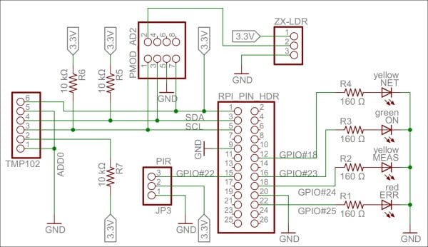
- The light sensor is a simple ZX-LDR analog sensor that will connect to a four-channel analog-to-digital converter (Digilent Pmod AD2). This is then connected to an I2C bus that will connect to the standard GPIO pins for I2C. Note that The I2C bus permits communication with multiple circuits using synchronous communication, employing a Serial Clock Line (SCL) and Serial Data Line (SDA) pin. This is a common way to communicate with integrated circuits.
- The temperature sensor (Texas Instruments TMP102) connects directly to the same I2C bus.
- The SCL and SDA pins on the I2C bus use recommended pull-up resistors to ensure they are in a high state when nobody actively pulls them down.
- The infrared motion detector (Parallax PIR sensor) is a digital input that can be connected to GPIO 22.
- Four LEDs will also be added to the board. One of these is green and is connected to GPIO 23. This will show when the application is running. The second one is yellow and is connected to GPIO 24. This will show when measurements are done. The third one is yellow and is connected to GPIO 18. This will show when an HTTP activity is performed. The last one is red and is connected to GPIO 25. This will show when a communication error occurs.
- The pins that control the LEDs are first connected to 160 Ω resistors before they are connected to the LEDs, and then to ground. All the hardware of the prototype board is powered by the 3.3 V source provided by Raspberry Pi. A 160 Ω resistor connected in series between the pin and ground ensures that the LED emits a bright light.
Tip
For an introduction to GPIO on Raspberry Pi, please refer to http://www.raspberrypi.org/documentation/usage/gpio/.
Two guides on GPIO pins can be found at http://elinux.org/RPi_Low-level_peripherals.
For more information, refer to http://pi.gadgetoid.com/pinout.
The following figure shows a circuit diagram of the prototype board:
Interacting with the hardware
Interaction with the hardware is done using corresponding classes defined in the Clayster.Library.RaspberryPi library. For instance, digital output is handled using the DigitalOutput class and digital input with the DigitalInput class. Devices connected to an I2C bus are handled using the I2C class. There are also other generic classes, such as ParallelDigitalInput and ParallelDigitalOutput, which handle a series of digital input and output at once.
The SoftwarePwm class handles a software-controlled pulse-width modulation output. The Uart class handles communication using the UART port available on Raspberry Pi. There’s also a subnamespace called Devices where device-specific classes are available.
In the end, all classes communicate with the static GPIO class, which is used to interact with the GPIO layer in Raspberry Pi.
Each class has a constructor that initializes the corresponding hardware resource, methods and properties to interact with the resource, and a Dispose method that releases the resource.
Tip
It is important that you release the hardware resources allocated before you terminate the application. Since hardware resources are not controlled by the operating system, the fact that the application is terminated is not sufficient to release the resources. For this reason, make sure you call the Dispose methods of all the allocated hardware resources before you leave the application. Preferably, this should be done in the final statement of a try-finally block.
Interfacing the hardware
The hardware interfaces to be used for the LEDs are as follows:
private static DigitalOutput executionLed = new DigitalOutput (23, true);
private static DigitalOutput measurementLed = new DigitalOutput (24, false);
private static DigitalOutput errorLed = new DigitalOutput (25, false);
private static DigitalOutput networkLed = new DigitalOutput (18, false);
Use a DigitalInput class for the motion detector:
private static DigitalInput motion = new DigitalInput (22);
With the temperature sensor on the I2C bus, which limits the serial clock frequency to a maximum of 400 kHz, interface it as follows:
private static I2C i2cBus = new I2C (3, 2, 400000);
private static TexasInstrumentsTMP102 tmp102 =
           new TexasInstrumentsTMP102 (0, i2cBus);
We interact with the light sensor using an analog-to-digital converter as follows:
private static AD799x adc =
         new AD799x (0, true, false, false, false, i2cBus);
Internal representation of sensor values
The sensor data values will be represented by the following set of variables:
private static bool motionDetected = false;
private static double temperatureC;
private static double lightPercent;
private static object synchObject = new object ();
Historical values will also be kept so that trends can be analyzed:
private static List<Record> perSecond = new List<Record> ();
private static List<Record> perMinute = new List<Record> ();
private static List<Record> perHour = new List<Record> ();
private static List<Record> perDay = new List<Record> ();
private static List<Record> perMonth = new List<Record> ();
Persisting data
Persisting data is simple. This is done using an object database. This object database analyzes the class definition of objects to persist and dynamically creates the database schema to accommodate the objects you want to store. The object database is defined in the Clayster.Library.Data library. You first need a reference to the object database, which is as follows:
internal static ObjectDatabase db;
Then, you need to provide information on how to connect to the underlying database. This can be done in the .config file of the application or the code itself. Specify a SQLite database and provide the necessary parameters in the code during the startup:
DB.BackupConnectionString = "Data Source=sensor.db;Version=3;";
DB.BackupProviderName = "Clayster.Library.Data.Providers."
                      + "SQLiteServer.SQLiteServerProvider";
Finally, you will get a proxy object for the object database. This object can be used to store, update, delete, and search for objects in your database:
db = DB.GetDatabaseProxy ("TheSensor");After doing this, the sensor won’t lose data if Raspberry Pi is restarted.
External representation of sensor values
To facilitate the interchange of sensor data between devices, you’ll need an interoperable sensor data format based on XML, provided in the Clayster.Library.IoT library. Here, the sensor data consists of a collection of nodes that report data ordered according to the timestamp.
For each timestamp, a collection of fields is reported. There are different types of fields available: numerical, string, date and time, timespan, Boolean, and enumeration-valued fields. Each field has a field name, field value of the corresponding type, an optional readout type, a field status, Quality of Service value, and localization information.
The Clayster.Library.IoT.SensorData namespace helps you export sensor data information by providing an abstract interface called ISensorDataExport. The same logic can later be used to export to different sensor data formats. The library also provides a class named ReadoutRequest that provides information about what type of data is desired. You can use this to tailor the data export to the desires of the requestor.
Exporting sensor data
The export starts by calling the Start() method on the sensor data export module and ends with a call to the End() method. Between these two, a sequence of StartNode() and EndNode() calls are made, one for each node to export.
To simplify the export, you can call another function to output data from an array of Record objects that contain the data. Use the same method to export the momentary values by creating a temporary Record object that would contain them:
private static void ExportSensorData (ISensorDataExport Output,
                                      ReadoutRequest Request)
{
  Output.Start ();
  lock (synchObject)
   {
    Output.StartNode ("Sensor");
    Export (Output, new Record[]
      {
        new Record (DateTime.Now, temperatureC, lightPercent, motionDetected)
      },ReadoutType.MomentaryValues, Request);

      Export (Output, perSecond, ReadoutType.HistoricalValuesSecond, Request);
      Export (Output, perMinute, ReadoutType.HistoricalValuesMinute, Request);
      Export (Output, perHour, ReadoutType.HistoricalValuesHour, Request);
      Export (Output, perDay, ReadoutType.HistoricalValuesDay, Request);
      Export (Output, perMonth, ReadoutType.HistoricalValuesMonth, Request);
      Output.EndNode ();
  }
  Output.End ();
}
Note that you need to check whether the corresponding readout type is desired by the client before you export data of this type.
Learn More:
How to use OpenCV with Raspberry Pi
How to build an IoT project using Raspberry Pi and Artik
The Export method exports an enumeration of Record objects. It first checks whether the corresponding readout type is desired by the client before exporting data of this type. The method also checks whether the data is within the requested time interval and that the fields are of interest to the client.
If a data field passes all these tests, it is exported by calling any of the instances of the overloaded method ExportField(), available on the sensor data export object. Fields are exported between the StartTimestamp() and EndTimestamp() method calls, defining the timestamp that corresponds to the fields being exported:
private static void Export(ISensorDataExport Output, IEnumerable History,
                           ReadoutType Type,ReadoutRequest Request)
{
  if((Request.Types & Type) != 0)
  {
   foreach(Record Rec in History)
   {
    if(!Request.ReportTimestamp (Rec.Timestamp))
     continue;

    Output.StartTimestamp(Rec.Timestamp);
    if (Request.ReportField("Temperature"))
      Output.ExportField("Temperature",Rec.TemperatureC, 1,"C", Type);
    if(Request.ReportField("Light"))
      Output.ExportField("Light",Rec.LightPercent, 1, "%", Type);

    if(Request.ReportField ("Motion"))
      Output.ExportField("Motion",Rec.Motion, Type);

    Output.EndTimestamp();
   }
  }
}
You can test the method by exporting some sensor data to XML using the SensorDataXmlExport class. It implements the ISensorDataExport interface. The result would look something like this if you export only momentary and historic day values:
<?xml version="1.0"?>
<fields xmlns="urn:xmpp:iot:sensordata">
  <node nodeId="Sensor">
    <timestamp value="2014-07-25T12:29:32Z">
      <numeric value="19.2" unit="C" automaticReadout="true"
                            momentary="true" name="Temperature"/>
      <numeric value="48.5" unit="%" automaticReadout="true"
                            momentary="true" name="Light"/>
      <boolean value="true" automaticReadout="true"
                            momentary="true" name="Motion"/>
    </timestamp>
    <timestamp value="2014-07-25T04:00:00Z">
      <numeric value="20.6" unit="C" automaticReadout="true"
                            name="Temperature" historicalDay="true"/>
      <numeric value="13.0" unit="%" automaticReadout="true"
                            name="Light" historicalDay="true"/>
      <boolean value="true" automaticReadout="true"
                            name="Motion" historicalDay="true"/>
    </timestamp>
   ...
  </node>
</fields>
If you enjoyed reading this tutorial and want to explore Internet of Things in detail, you can explore the book, Learning Internet of Things by Peter Wahr. The book follows a hands-on approach and demonstrates the building of several IoT projects, including actuators, cameras, controllers, and more. If you’re an IoT enthusiast or a developer keen on learning the fundamentals of IoT, this book is a must-have in your kitty.
| Published on Java Code Geeks with permission by Francesco Azzola, partner at our JCG program. See the original article here: Learn IoT creating a sensor project with Raspberry Pi and sensors Opinions expressed by Java Code Geeks contributors are their own. |