Ignite Baseline Topology or BLT represents a set of server nodes in the cluster that persists data on disk.

Where, N1-2 and N5 server nodes are the member of the Ignite clusters with native persistence which enable data to persist on disk. N3-4 and N6 server nodes are the member of the Ignite cluster but not a part of the baseline topology.
The nodes from the baseline topology are a regular server node, that store’s data in memory and on the disk, and also participates in computing tasks. Ignite clusters can have different nodes that are not a part of the baseline topology such as:
- Server nodes that are not used Ignite native persistence to persist data on disk. Usually, they store data in memory or persists data to a 3rd party database or NoSQL. In the above equitation, node N3 or N4 might be one of them.
- Client nodes that are not stored shared data.
To better understand the baseline topology concept, let’s start at the beginning and try to understand its goal and what problem it helps us solve.
The database like Ignite is designed to support massive data storage and processing. Ignite databases are highly scalable and fault-tolerant. This high scalability feature of the Ignite brings a few challenges for the database administrator, such as: how to manage a cluster? How to add/remove nodes correctly or how to rebalance data after add/remove nodes? Because Ignite cluster with a multitude of a node can significantly increase the complexity of the data infrastructure. Let’s look at by the example of Apache Ignite.
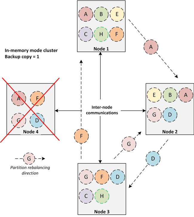
Ignite in-memory mode cluster concept is very simple. There are no master or dedicated node in the cluster, and every node is equal. Each node stores a subset of partitions and can be participated in distributed computing or deploy any services. In case of any node failures, user requests served by the other nodes, and the data of the failed nodes will be no longer available. The Ignite cluster management operations are very similar as follows:
- To run a cluster, start all nodes.
- To expand the cluster topology, add some nodes.
- To reduce the cluster topology, remove some nodes.
Portions of this article were taken from the book The Apache Ignite book. If it got you interested, check out the rest of the book for more helpful information.
Data redistributes between nodes automatically. Depending on the backup copy configuration of the caches, data partitions moves from one node to another.
In the persistence mode, the node keeps their state even after the restart. During any read operation, data is read from the disk and restores the node state. Therefore, unlike in-memory mode, restart of a node in persistence mode does not need to redistributed data from one node to another. The data during node failure will be restored from the disk. This strategy opens up the opportunities to not only preventing moving a massive amount of data during node failure but also reduce the startup times of the entire cluster after a restart. So, we need to distinguish somehow these nodes that can save their state after restart. In other words, the Ignite baseline topology provides this capability.
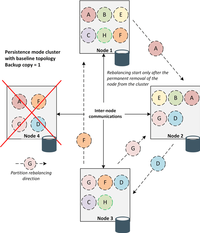
In a nutshell, Ignite baseline topology is a collection of nodes that have been configured for storing persistence data on disk. Baseline topology tracks the history of the topology changes and prevents data discrepancies in the cluster during recovery. Let’s resume the goals of the baseline topology:
- Avoid redundant data rebalancing if a node is being rebooted.
- Automatically activate a cluster once all the nodes of the baseline topology have joined after a cluster restart.
- Prevent the data inconsistencies in the case of split-brain.
Apache Ignite provides a command line (CLI) tool that allows to monitor and manage a cluster Baseline topology. In this article, we will review several common scenarios of Baseline topology administration with this tool when Ignite persistence is used.
The ./control.sh command line script can be found under /bin folder of an Apache Ignite distribution directory. The primary goal of this script (tool) is to activate/deactivate and management of a set of nodes that represent the baseline topology. However, this tool is a multi-purpose tool and can be actively used for monitoring the cache states or detecting any transaction locks that could occur in the entire cluster.
Preparing the sandbox. As we stated before the script that runs the tool is located in the {Ignite_home}/bin folder and called control.sh. There are versions of the script for Unix (control.sh) and Windows (control.bat). For demonstration purpose I will use the following configurations:
| Name | Description |
|---|---|
| OS | MacOS, you can use Windows or Linux operating system by your choice. |
| Ignite version | 2.6.0 or above. |
| The number of Ignite nodes | 3 nodes in a single host. |
| JVM | 1.8 |
| TCP discovery | Multicast |
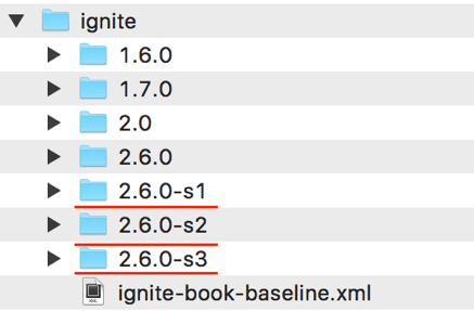
Step 1. We are going to run three Ignite nodes on persistence mode in a single host. By defaults, Ignite creates a WORK directory under the IGNITR_HOME folder for storing WAL archives and log files. Download the Ignite distribution and unarchive it in 3 different directories on your operating system, for example/usr/ignite/2.6.0-s1, /usr/ignite/2.6.0-s2, /usr/ignite/2.6.0-s3. You should have a similar folder hierarchy as shown in figure 4.
Note that, it is the simplest way to run a few nodes with persistence enable in a single host without any extra configuration. However, you can configure Ignite such a way that allows you to run a few Ignite nodes with different WAL archive folders.
Step 2. To enable the persistence store, we use the Ignite data storage configuration through Spring. Create an XML file with name ignite-book-baseline.xml and copy the following content in it.
<beans xmlns:xsi="http://www.w3.org/2001/XMLSchema-instance" xmlns="http://www.springframework.org/schema/beans" xsi:schemalocation="
        http://www.springframework.org/schema/beans
        http://www.springframework.org/schema/beans/spring-beans.xsd">
    <bean class="org.apache.ignite.configuration.IgniteConfiguration" id="ignite.cfg">
        <property name="cacheConfiguration">
            <list>
                <bean class="org.apache.ignite.configuration.CacheConfiguration">
                    <property name="name" value="TestCache">
                    <property name="atomicityMode" value="ATOMIC">
                    <property name="backups" value="1">
                </property></property></property></bean>
            </list>
        </property>
        <!-- Enabling Apache Ignite Persistent Store. -->
        <property name="dataStorageConfiguration">
            <bean class="org.apache.ignite.configuration.DataStorageConfiguration">
                <property name="defaultDataRegionConfiguration">
                    <bean class="org.apache.ignite.configuration.DataRegionConfiguration">
                        <property name="persistenceEnabled" value="true">
                        <property name="metricsEnabled" value="true">
                    </property></property></bean>
                </property>
            </bean>
        </property>

        <property name="discoverySpi">
            <bean class="org.apache.ignite.spi.discovery.tcp.TcpDiscoverySpi">
                <property name="ipFinder">

                    <bean class="org.apache.ignite.spi.discovery.tcp.ipfinder.multicast.TcpDiscoveryMulticastIpFinder">
                        <property name="addresses">
                            <list>
                                <value>127.0.0.1:47500..47509</value>
                            </list>
                        </property>
                    </bean>
                </property>
            </bean>
        </property>
    </bean>
</beans>
Save the file somewhere in your filesystem.
Step 3. We will be starting each Ignite server node one at a time starting with our first Ignite node. Open a terminal and change the IGNITE_HOME directory to the folder where you unarchive the Ignite distribution for the Ignite node 1.
export IGNITE_HOME=PATH_TO_THE_IGNITE_NODE_ONE/ignite/2.6.0-s1
Now, start the first Ignite node with the following command:
ignite.sh /PATH_TO_THE_SPRING_CONFIG_FILE/ignite/ignite-book-baseline.xml
Your output on the console should resemble like this:
ver. 2.6.0#20180710-sha1:669feacc
2018 Copyright(C) Apache Software Foundation
Ignite documentation: http://ignite.apache.org Quiet mode.
^-- Logging to file '/usr/ignite/2.6.0-s1/work/log/ignite-f0ef6ecc.0.log'
Topology snapshot [ver=1, servers=1, clients=0, CPUs=8, offheap=3.2GB, heap=1.\
^-- Node [id=F0EF6ECC-D692-4862-9414-709039FE00CD, clusterState=INACTIVE] Data Regions Configured:
^-- default [initSize=256.0 MiB, maxSize=3.2 GiB, persistenceEnabled=true]
Inspect the logs displays on the console, log messages confirm that our first Ignite server is up and running and the persistence mode is enabled. Now do the same thing again for the second Ignite node.
export IGNITE_HOME=PATH_TO_THE_IGNITE_NODE_ONE/ignite/2.6.0-s2
ignite.sh /PATH_TO_THE_SPRING_CONFIG_FILE/ignite/ignite-book-baseline.xml
At this moment, you can see that the 2nd Ignite node started on persistence mode and joined to the cluster. You should see very similar messages in the terminal as shown below.
[16:13:35] >>> Ignite cluster is not active (limited functionality available). Use contro\ l.(sh|bat) script or IgniteCluster interface to activate.
[16:13:35] Topology snapshot [ver=2, servers=2, clients=0, CPUs=8, offheap=6.4GB, heap=2.\ 0GB]
[16:13:35] ^-- Node [id=6DB02F31-115C-41E4-BECC-FDB6980F8143, clusterState=INACTIVE] [16:13:35] Data Regions Configured:
[16:13:35] ^-- default [initSize=256.0 MiB, maxSize=3.2 GiB, persistenceEnabled=true]
Ignite also warned that the cluster is not activated yet and you have to activate the cluster by using control.sh script. Let’s activate the cluster and creates a few tables for storing data.
Step 4. Before we activate the cluster, let’s consider specific features of the control.sh tool. The control.sh script currently supports the following commands:
| Command | Description |
|---|---|
| –activate | This command switches the cluster into an active state. In this case, if there is no baseline topology exists in the cluster, a new baseline will be created during activation of the cluster. The new baseline topology will include all of the connected nodes in the cluster topology. |
| –deactivate | Deactivate the cluster. Limited functionality will be available in this state. |
| –state | Print the current cluster state. |
| –baseline | This command is designed to manage the baseline topology. When this command used without any parameters, it prints the current cluster baseline topology information. The following parameters can be used with this command: add, remove, set, and version. |
To invoke a specific command, use the following pattern:
UNIX/LINUX/MacOS
$IGNITE_HOME/bin/control.sh
Now, activate the cluster. Run the following command:
$IGNITE_HOME/bin/control.sh
If the command succeeds, you should see the following messages in the console.
Control utility [ver. 2.6.0#20180710-sha1:669feacc] 2018 Copyright(C) Apache Software Foundation
User: shamim
--------------------------------------------------------------------------------
Cluster activated
At this moment, you can also use the –state command to check the current cluster state. The–state command should return a message that the cluster is activated.
Step 5. Now, create a table and populate some data. We use the SQLLINE tool to connect to the cluster. Run the following command to start the SQLLINE tool:
sqlline.sh --color=true --verbose=true -u jdbc:ignite:thin://127.0.0.1/
Create a table named EMP and insert 1000 rows into the table. Use the following DDL script to create the EMP table as follows:
CREATE TABLE IF NOT EXISTS EMP
(
 empno LONG, ename VARCHAR, job VARCHAR, mgr INTEGER, hiredate DATE,
sal LONG,
comm LONG,
deptno LONG,
CONSTRAINT pk_emp PRIMARY KEY (empno)
) WITH "template=partitioned,CACHE_NAME=EMPcache";
Next, use the EMP_001.sql script from the GitHub repository to insert 1000 entries into the table.
0: jdbc:ignite:thin://127.0.0.1/> !run /PATH_TO_THE_FILE/the-apache-ignite-book/chapters/\ chapter-10/baseline/EMP_001.sql
The above command inserts 1000 entries into the EMP table or EMPcache. Use the visor CLI tools to see the size of the cache into the entire cluster. Run the command cache -a in the IgniteVisor console. The command should return the following output as shown in figure 5.
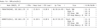
Take a look at the column named SIZE. This column clarifies the number of entries stored into each node. In our case, one of our nodes contains 504 entries, and the other one contains 496 entries into the EMPcache cache.
Step 6. So far, we have launched only 2 Ignite nodes and created a baseline topology in the cluster. Let’s start another Ignite node. Do the same thing again as before for the 3rd Ignite node.
export IGNITE_HOME=PATH_TO_THE_IGNITE_NODE_ONE/ignite/2.6.0-s3
ignite.sh /PATH_TO_THE_SPRING_CONFIG_FILE/ignite/ignite-book-baseline.xml
Logs on the console should confirm you that the node is started on persistence mode successfully. Moreover, you should get a warning on the console that the local node is not included in Baseline Topology and will not be used for persistent data storage. Now we can play with the –baseline command. Let’s run the command without any parameter as follows:
$IGNITE_HOME/bin/control.sh --baseline
The output might be as follows:
shamim:~ shamim$ control.sh --baseline
Control utility [ver. 2.6.0#20180710-sha1:669feacc] 2018 Copyright(C) Apache Software Foundation
User: shamim --------------------------------------------------------------------------------
 Cluster state: active
Current topology version: 6
Baseline nodes:
ConsistentID=1640f655-4065-438c-92ca-478b5df91def, STATE=ONLINE ConsistentID=d8b04bc3-d175-443c-b53f-62512ff9152f, STATE=ONLINE
--------------------------------------------------------------------------------
Number of baseline nodes: 2
Other nodes: ConsistentID=3c2ad09d-c835-4f4b-b47a-43912d04d30e
Number of other nodes: 1
The above baseline information shows the cluster state, topology version, nodes with their consistent IDs that are part of the baseline topology as well as those that are not part of the baseline topology. Here, the number of baseline nodes is 2, and the baseline consists of our 1st and 2nd Ignite node.
Sometime it may happen that, during the first cluster activation the baseline topology was not created. In such cases, the –baseline command will return a message like “Baseline nodes not found.” In this situation stop the 3rd node and waits for a few seconds. Then set the baseline topology manually by using the numerical cluster topology version as follows:
control.sh --baseline version topologyVersion
In the above command, replace the topologyVersion with the actual topology version. You can find the topology version in any Ignite node console as shown below:
Topology snapshot [ver=6, servers=3, clients=0, CPUs=8, offheap=9.6GB, heap=3.0GB]
Pick the latest topology snapshot version from the console.
In this stage, our 3rd Ignite node is not the part of our baseline topology. This node will not be used for persistent data storage. It means, if we will create any new tables and insert data into it, the node will not store any data for the new table. Let’s verify the concept.
Step 7. Create a new table DEPT with the following DDL script:
CREATE TABLE IF NOT EXISTS DEPT (
deptno LONG,
dname VARCHAR,
loc VARCHAR,
CONSTRAINT pk_dept PRIMARY KEY (deptno)
) WITH "template=partitioned,CACHE_NAME=DEPTcache";
Also, insert 100 departments by using the DEPT.SQL. The DEPT.SQL script is available at the GitHub repository.
0: jdbc:ignite:thin://127.0.0.1/> !run /PATH_TO_THE_FILE/github/the-apache-ignite-book/ch\ apters/chapter-10/baseline/DEPT.sql
Now, run the command cache -a in the visor console which should print a similar output shown in figure 6.
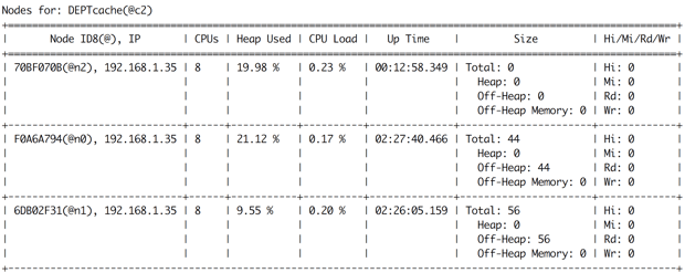
The above figure confirms that the 3rd node does not contain any persistence data. However, the node that not a part of the baseline topology can participate in any in-memory computing.
Step 8. Next, let’s add the new empty node to the baseline topology to hold persistence data. Invoke the command –baseline add
to add the new node to the existing baseline.
control.sh --baseline add 3c2ad09d-c835-4f4b-b47a-43912d04d30e
In the above command, replace the consistent id 3c2ad09d-c835-4f4b-b47a-43912d04d30ewith your consistentId of the 3rd Ignite node. After completing the –baseline add command, a message will confirm that the new baseline topology contains 3 nodes.
Cluster state: active
Current topology version: 10
Baseline nodes:
ConsistentID=1640f655-4065-438c-92ca-478b5df91def, STATE=ONLINE
ConsistentID=3c2ad09d-c835-4f4b-b47a-43912d04d30e, STATE=ONLINE
ConsistentID=d8b04bc3-d175-443c-b53f-62512ff9152f, STATE=ONLINE
-------------------------------------------------------------------------------- Number of baseline nodes: 3
Other nodes not found.
After forming the new baseline topology from 3 nodes, a data rebalancing will proceed immediately. The new empty node (in our case it’s the 3rd node) will receive his portion of data from other nodes. If you run the cache -a command in Ignite Visor CLI again, you can confirm the data rebalancing. Figure 7 shows the result of the data rebalancing after adding the 3rd node in the baseline topology.
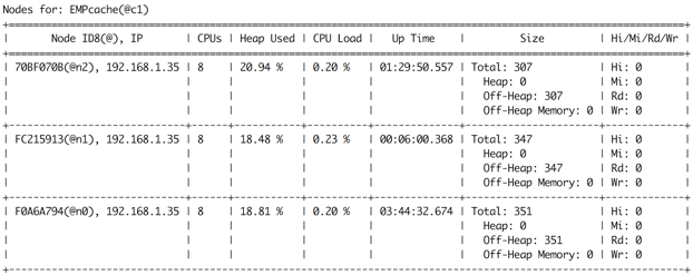
Now each node stores almost evenly partition of entries (about 300 entries) for cache EMPcache. However, what will happen if one of the baseline topology nodes will be restarted? Let’s stop one node and try to insert some data into the table EMP.
Step 9. Stop the 2nd node by hitting the key CRTL+X. Execute the command –baseline without any parameter to print the state of the baseline topology.
control.sh --baseline
The above command will display the current baseline topology status very similar to the next message:
--------------------------------------------------------------------------------
Cluster state: active
Current topology version: 11
Baseline nodes:
ConsistentID=1640f655-4065-438c-92ca-478b5df91def, STATE=OFFLINE
ConsistentID=3c2ad09d-c835-4f4b-b47a-43912d04d30e, STATE=ONLINE
ConsistentID=d8b04bc3-d175-443c-b53f-62512ff9152f, STATE=ONLINE
--------------------------------------------------------------------------------
Number of baseline nodes: 3
Other nodes not found
One of the nodes in offline as expected. Now try to insert some data into the EMP table by SQLLINE tool as follows:
insert into EMP (empno, ename, job, mgr, hiredate, sal, comm, deptno) values (2009, 'Sall\ ie', 'Sales Associate', 96, null, 3619, 34, 78);
insert into EMP (empno, ename, job, mgr, hiredate, sal, comm, deptno) values (2010, 'Cori\ ', 'Human Resources Manager', 65, null, 1291, 86, 57);
insert into EMP (empno, ename, job, mgr, hiredate, sal, comm, deptno) values (2011, 'Myrt\ le', 'VP Quality Control', 88, null, 5103, 21, 48);
insert into EMP (empno, ename, job, mgr, hiredate, sal, comm, deptno) values (2012, 'Ches\ ', 'Desktop Support Technician', 46, null, 6352, 29, 21);
You should notice that a few inserts statement failed with errors which shown in the next snippet.
Caused by: class org.apache.ignite.internal.cluster.ClusterTopologyServerNotFoundExceptio\ n: Failed to map keys for cache (all partition nodes left the grid).
at org.apache.ignite.internal.processors.cache.distributed.dht.atomic.GridNearAtomicSing\ leUpdateFuture.mapSingleUpdate(GridNearAtomicSingleUpdateFuture.java:562)
This error occurred because we have no backup copies for our EMP table. The node that should store the data has been stopped, and Ignite cannot be able to store the data. To avoid such a situation, consider a cache/table with one backup. If one node fails, it will lose no data. For now, we have a few options:
- Reboot the offline node as soon as possible with minimal downtime for preventing data loss.
- Remove the offline node from the baseline topology and rebalancing the data.
Step 10. Let’s remove the offline node from the baseline topology. Execute the following command:
Caused by: class control.sh --baseline remove 1640f655-4065-438c-92ca-478b5df91def
After completing the remove command, the baseline topology changed excluding the stopped node. Note that, By removing a node from the baseline topology, you acknowledge that you will no longer be able to use the data stored on that node after its restart. At this moment, no error will occur during data manipulation into the cluster. You can insert new entries or update existing entries into the cache successfully.
Note that, the node that you want to remove from the baseline topology should be disconnected from the cluster before removing from the baseline. Otherwise, the error “Failed to remove nodes from baseline” occurs, specifying the nodes that you have to stop before deleting from the baseline.
In addition to topology management, control.sh script can also be used for monitoring and control a cluster state which is well documented in Ignite site. So, please refer to the control script section of the Ignite documentation for more information.
| Published on Java Code Geeks with permission by Shamim Bhuiyan, partner at our JCG program. See the original article here: Apache Ignite Baseline Topology by Examples Opinions expressed by Java Code Geeks contributors are their own. |